

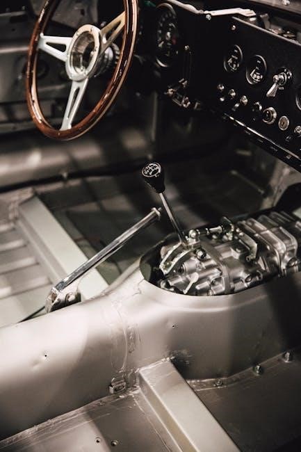
Six-speed manual transmissions are favored by enthusiasts for enhanced control and engagement‚ offering a direct connection to the driving experience.
Understanding these systems‚ aided by a diagram‚ simplifies their complex inner workings‚ revealing how six distinct gears optimize performance and efficiency.
A 6-speed manual transmission diagram visually explains gear ratios and shifting patterns‚ crucial for both drivers and mechanics alike.
1.1 Overview of Manual Transmissions
Manual transmissions‚ a cornerstone of automotive engineering‚ empower drivers with direct control over gear selection and vehicle speed. Unlike automatic transmissions‚ which handle shifting automatically‚ manual systems require the driver to operate a clutch pedal and shift lever. This direct engagement provides a more connected and involved driving experience‚ favored by many automotive enthusiasts.
At its core‚ a manual transmission utilizes a series of gears to alter the ratio between engine speed and wheel speed. Lower gears provide increased torque for acceleration and climbing hills‚ while higher gears offer improved fuel efficiency at cruising speeds. A 6-speed manual transmission diagram illustrates these gears and their relationships‚ showcasing how power is transferred from the engine to the wheels.
The fundamental principle involves disengaging the engine from the drivetrain using the clutch‚ selecting the desired gear‚ and then re-engaging the clutch to smoothly transfer power. Understanding this process‚ and visualizing it with a diagram‚ is key to mastering the art of driving a manual vehicle. The 6-speed configuration offers a wider range of gear ratios‚ enhancing both performance and fuel economy.
1.2 Why Choose a 6-Speed Manual?
Opting for a 6-speed manual transmission delivers a uniquely engaging driving experience‚ offering greater control and a more visceral connection to the vehicle. Compared to fewer-speed transmissions‚ a 6-speed provides closer gear ratios‚ allowing the engine to operate more consistently within its optimal power band. A diagram of this system reveals the intricacies of these ratios.
This translates to improved acceleration‚ enhanced fuel efficiency‚ and more precise control during spirited driving. The wider range of gears also allows for a more comfortable cruising experience at highway speeds‚ reducing engine strain and noise. Examining a 6-speed manual transmission diagram clarifies how each gear contributes to overall performance.
For driving enthusiasts‚ the 6-speed offers a level of involvement that automatic transmissions simply cannot match. The ability to select the perfect gear for any situation provides a sense of mastery and control. Furthermore‚ a well-maintained 6-speed manual can offer increased reliability and longevity‚ as evidenced by detailed schematics and diagrams available for repair and maintenance.

Core Components of a 6-Speed Manual Transmission
A 6-speed manual transmission diagram showcases the vital interplay of the input shaft‚ countershaft‚ output shaft‚ gears‚ and synchromesh mechanisms.
These components work in harmony to efficiently transfer power‚ as illustrated in detailed schematics.

2.1 Input Shaft and Clutch
The input shaft‚ prominently featured in a 6-speed manual transmission diagram‚ is the initial receiver of engine power. It’s directly connected to the engine’s flywheel via the clutch assembly.
The clutch’s primary function‚ clearly depicted in diagrams‚ is to engage or disengage the engine’s power from the transmission. When the clutch pedal is pressed‚ it separates the engine from the input shaft‚ allowing for gear changes.
A diagram illustrates how the clutch disc‚ pressure plate‚ and release bearing work together. Failure to fully depress the clutch‚ as highlighted in troubleshooting guides‚ can lead to increased shifting effort and premature wear of transmission components.
The input shaft then transmits this power to the countershaft‚ initiating the gear selection process. Understanding this initial power transfer‚ as shown in a detailed 6-speed manual transmission diagram‚ is crucial for comprehending the entire system’s operation.
Proper clutch operation is vital for smooth gear transitions and longevity of the transmission.
2.2 Countershaft (Lay Shaft)
The countershaft‚ or lay shaft‚ is a central component visualized in any 6-speed manual transmission diagram. It receives power from the input shaft and distributes it to the various gear sets.
A diagram reveals that the countershaft constantly spins when the engine is running and the clutch is engaged. Different gears on the countershaft mesh with corresponding gears on the input and output shafts.
These gears‚ as illustrated in a detailed diagram‚ have varying sizes‚ creating different gear ratios. The selection of a specific gear ratio is achieved by synchronizing the desired gear on the output shaft with the rotating countershaft.
Understanding the countershaft’s role‚ as shown in a 6-speed manual transmission diagram‚ is key to grasping how different speeds and torque levels are achieved. It’s the intermediary that allows the driver to select the optimal power delivery for various driving conditions.
Its constant rotation is fundamental to the transmission’s functionality.
2.3 Output Shaft
The output shaft‚ clearly depicted in a 6-speed manual transmission diagram‚ is the final component in the power delivery chain. It transmits the adjusted torque from the transmission to the driveshaft‚ ultimately powering the wheels.
A detailed diagram illustrates how the output shaft receives power from the countershaft via the selected gear set. Different gears on the output shaft provide varying output speeds and torque levels.
As shown in a 6-speed manual transmission diagram‚ the output shaft’s rotation speed is directly related to the gear ratio selected. Lower gears provide higher torque for acceleration‚ while higher gears offer lower engine speeds for efficient cruising.
The diagram also highlights the splined end of the output shaft‚ which connects to the driveshaft. Understanding the output shaft’s function‚ as visualized in the diagram‚ is crucial for comprehending how the transmission translates engine power into vehicle motion.
It’s the final link in the mechanical process.
2.4 Gears and Synchromesh
A 6-speed manual transmission diagram vividly showcases the intricate arrangement of gears‚ each designed for a specific speed and torque output. These gears‚ meshing with the countershaft and output shaft‚ are fundamental to the transmission’s operation.
The diagram also reveals the crucial role of synchromesh mechanisms. These devices‚ positioned between the gears‚ are essential for smooth and quiet gear changes. They equalize the speeds of the engaging gears before full contact.
As illustrated in a detailed diagram‚ synchromesh utilizes friction to synchronize speeds‚ preventing grinding and damage. Without synchromesh‚ shifting would be difficult and potentially destructive.
The 6-speed configuration means six distinct gear pairs‚ each contributing to a different gear ratio. The diagram clearly shows how these ratios impact vehicle performance‚ offering a balance between acceleration and fuel efficiency. Understanding gear and synchromesh interaction‚ as shown in the diagram‚ is key to appreciating manual transmission technology.
Detailed 6-Speed Manual Transmission Diagram Breakdown
A 6-speed manual transmission diagram visually deciphers the gearbox’s internal workings‚ illustrating gear ratios and shifting patterns for optimal understanding and maintenance.
This diagram aids in grasping power transmission through gears‚ enhancing vehicle control and efficiency.
3.1 Gear Ratio Explanation
Gear ratios within a 6-speed manual transmission diagram are fundamental to understanding how the vehicle translates engine power into usable force at the wheels. Each gear represents a different ratio between the engine’s rotational speed and the wheels’ rotational speed.

Lower gears (like 1st and 2nd) have higher numerical ratios‚ providing more torque for acceleration but limiting top speed. Conversely‚ higher gears (5th and 6th) have lower numerical ratios‚ prioritizing fuel efficiency and higher speeds at the expense of immediate acceleration.
The diagram illustrates how these ratios are achieved through different sized gears meshing together. A larger gear driving a smaller gear results in a higher ratio‚ increasing torque. Examining the diagram helps visualize how selecting different gears alters the mechanical advantage‚ impacting both acceleration and fuel economy. Understanding these ratios is key to efficient driving and maximizing the vehicle’s performance potential.
The 6-speed configuration offers a wider range of ratios‚ allowing for finer control and optimization for various driving conditions compared to transmissions with fewer gears.
3.2 Shifting Pattern Visualization
A core element of any 6-speed manual transmission diagram is the clear depiction of the shifting pattern. This diagram visually represents the spatial arrangement of gears‚ guiding the driver on how to select each gear using the shift lever.
Typically‚ a “H-pattern” is used‚ with each gear position corresponding to a specific location within the ‘H’. The diagram clearly shows the sequence for shifting between gears‚ including the position for reverse‚ which often requires a specific maneuver like pressing down on the lever.
Understanding this pattern is crucial for smooth and efficient driving. The diagram helps drivers internalize the layout‚ reducing hesitation and preventing mis-shifts. It also illustrates the relationship between gear positions and the corresponding gear ratios‚ enhancing overall control.
A well-defined shifting pattern diagram is invaluable for both novice and experienced drivers‚ promoting confident and precise gear changes within the 6-speed system.
3.3 Identifying Key Components on the Diagram
A comprehensive 6-speed manual transmission diagram doesn’t just show the shifting pattern; it meticulously labels the core components. These include the input shaft‚ receiving power from the clutch‚ and the output shaft‚ delivering power to the wheels.
The diagram clearly identifies the countershaft (lay shaft)‚ crucial for transferring power between the input and output shafts. It also highlights the various gears themselves‚ showcasing their different sizes and positions. Synchromesh mechanisms‚ vital for smooth gear engagement‚ are also typically labeled.
Understanding the location and function of each component‚ as illustrated on the diagram‚ is essential for troubleshooting and repair. The diagram often includes annotations explaining the role of each part in the overall transmission process.
By visually connecting the components to their functions‚ the diagram transforms a complex system into an understandable and accessible representation of the 6-speed gearbox.

The Shifting Mechanism
The shifting mechanism‚ visualized on a diagram‚ utilizes linkages and cables to translate driver input into gear selection within the transmission.
Shift forks and selector rods precisely engage gears‚ enabling smooth transitions.
4.1 Shift Linkage and Cables
Shift linkage and cables are vital components illustrated in a 6-speed manual transmission diagram‚ responsible for transmitting the driver’s gear selection from the shift lever to the transmission itself. These systems convert the lever’s motion into precise movements within the gearbox.
Typically‚ older vehicles employ direct linkages – rigid rods connecting the lever to the transmission. Modern vehicles increasingly utilize cables‚ offering greater flexibility in mounting the shifter and reducing vibration transfer to the cabin. A diagram clearly shows how these cables route and connect.
The linkage or cable system must be properly adjusted to ensure accurate gear engagement. Misalignment can lead to difficulty shifting‚ grinding noises‚ or even inability to select certain gears. Examining a detailed diagram helps understand the correct geometry and adjustment points. Proper function relies on secure connections and minimal play within the system‚ all of which are visually represented in a comprehensive transmission diagram.
4.2 Shift Forks and Selector Rods
A 6-speed manual transmission diagram prominently features shift forks and selector rods‚ the internal mechanisms directly engaging the gears. Selector rods‚ moved by the shift linkage or cables‚ translate external input into internal action within the transmission.
These rods actuate the shift forks‚ which are y-shaped levers that slide the synchronizers along the main and countershafts. The diagram illustrates how each fork corresponds to a specific gear. Precise movement is crucial; incorrect engagement causes grinding or failure to shift.
Understanding the arrangement of shift forks and selector rods‚ as shown in a detailed diagram‚ is essential for diagnosing shifting problems. Wear or damage to these components can result in sloppy gear changes or complete inability to select a gear. A clear visual representation aids in identifying potential issues and guiding repair procedures‚ ensuring smooth and accurate gear selection.

Common Issues and Troubleshooting
A 6-speed manual transmission diagram aids in diagnosing problems like clutch failure‚ shifting difficulties‚ and unusual noises.
Identifying components visually helps pinpoint the source of issues‚ streamlining the troubleshooting process.
5.1 Clutch Problems
Clutch issues are frequently encountered with 6-speed manual transmissions‚ and a detailed diagram proves invaluable for diagnosis. A diagram clearly illustrates the clutch’s position within the system‚ showing the pressure plate‚ clutch disc‚ and release bearing.
Common problems include a worn clutch disc‚ leading to slippage during acceleration‚ or a failing pressure plate‚ causing incomplete engagement. A diagram helps visualize how these components interact and identify potential failure points. Difficulty fully depressing the clutch pedal‚ as highlighted in troubleshooting guides‚ can also cause issues.
Furthermore‚ a diagram can assist in understanding the clutch linkage and cables‚ identifying potential binding or adjustment problems. Failure to fully engage the clutch can prematurely wear transmission components or even cause damage. Inspecting the diagram alongside physical inspection allows for a more accurate assessment of the clutch system’s health and facilitates targeted repairs.
5.2 Difficulty Shifting Gears
Difficulty shifting gears in a 6-speed manual transmission often stems from issues within the shifting mechanism‚ and a diagram is essential for pinpointing the source. The diagram showcases the shift linkage‚ cables‚ shift forks‚ and selector rods – all critical components for smooth gear changes.
Problems can range from worn or damaged shift cables causing imprecise movements‚ to bent shift forks preventing full gear engagement. A diagram helps trace the path of the shift action‚ revealing potential obstructions or points of failure.
As noted in troubleshooting resources‚ incomplete clutch disengagement can also mimic shifting problems; the diagram reinforces the clutch’s role in this process. Furthermore‚ internal transmission issues‚ like worn synchronizers‚ can manifest as difficulty selecting specific gears. Utilizing the diagram alongside a methodical inspection allows for a systematic approach to diagnosing and resolving these shifting challenges.
5.3 Transmission Noises
Unusual transmission noises in a 6-speed manual transmission can indicate a variety of internal problems‚ and a detailed diagram is invaluable for diagnosis. The diagram illustrates the intricate arrangement of gears‚ shafts‚ and bearings‚ allowing for a focused investigation of potential noise sources.
Whining sounds often point to worn bearings on the input shaft‚ countershaft‚ or output shaft – all clearly visible on the diagram. Grinding noises during shifting typically suggest failing synchronizers‚ components also identifiable within the diagram’s depiction of the gearsets.
Clunking sounds could indicate excessive play in the gear teeth or damaged differential components. By referencing the diagram‚ technicians can isolate the area generating the noise and determine the necessary repairs. Understanding the transmission’s internal layout‚ as shown in the diagram‚ is crucial for accurate noise identification and effective resolution.

Maintenance and Repair
Regular fluid checks and changes‚ guided by a 6-speed manual transmission diagram‚ are vital for longevity.
The diagram aids in locating fill and drain plugs‚ ensuring correct fluid levels and optimal performance.
Clutch adjustment‚ visualized with the diagram‚ maintains proper engagement.
6.1 Fluid Checks and Changes
Regular fluid checks are paramount for maintaining the health of your 6-speed manual transmission‚ and a detailed diagram is an invaluable tool in this process. The diagram clearly illustrates the location of the fill and drain plugs‚ essential for accurately performing fluid level checks and changes.
Typically‚ a manual transmission utilizes a specific type of gear oil – consult your vehicle’s owner’s manual for the correct specification. To check the fluid level‚ locate the fill plug (identified on the diagram) and remove it. The fluid level should be at the bottom of the fill plug opening.
When changing the fluid‚ ensure the transmission is warm‚ but not hot. Drain the old fluid completely using the drain plug (also shown on the diagram)‚ and then refill with the specified amount of new fluid. Always double-check the diagram to confirm plug locations and torque specifications to avoid damage.
Consistent fluid maintenance‚ aided by the diagram‚ prevents wear and ensures smooth shifting.

6.2 Clutch Adjustment
Proper clutch adjustment is crucial for smooth shifting and preventing premature wear in a 6-speed manual transmission‚ and a diagram can greatly simplify this process. The diagram will illustrate the clutch linkage components – including the pedal‚ cable (if equipped)‚ and release fork – highlighting adjustment points.
Incorrect adjustment can lead to issues like difficulty shifting‚ clutch slippage‚ or a clutch that doesn’t fully disengage. Typically‚ adjustment involves ensuring a specific amount of free play in the clutch pedal. Refer to your vehicle’s service manual and the diagram for the precise specification.
For cable-operated clutches‚ adjustment is usually made via a threaded adjuster on the cable itself. Hydraulic systems may require bleeding to remove air. Always consult the diagram to understand the system’s layout before making any adjustments.
A correctly adjusted clutch‚ guided by the diagram‚ ensures optimal performance and longevity.